


Every manufacturing company has two most basic rival department – one who does the design of the product and one who manufacture those products as per the design.
If both of these rivals are not on the same page then there will be the backbiting and finger-pointing. Believe me, this can escalate easily into something worse.
We can eliminate this rift if design engineers keep certain manufacturing consideration in mind while they design the product. In this series of post, we will look into guidelines for design engineers. Let’s start with Fillets/Round Edges and Chamfer.
What is the difference between Fillet and Chamfer?
The basic one-liner answer for this question is Fillets is the round corner of parts either outside or inside edges.
Fillets produce the parts with better flow and distribute the stress over the border area. Factors like low-stress concentration, eliminating sharp edges which can cause injury during assembly and inspection makes this machining operation significant in part design activity.
On the other hand, the chamfer is the sloped/angled corner or edges. Unlike fillet, when it comes to stress concentration, chamfer cannot be preferred as they have sharp corners.
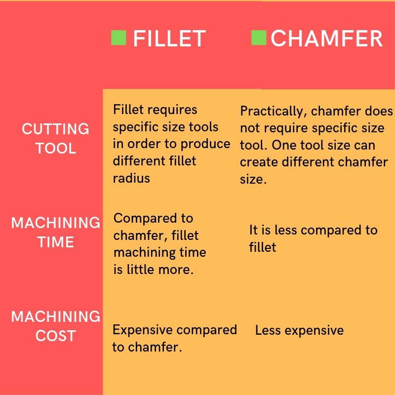
Chamfer made on the hole is used as a lead-in for pins and screws. Below table is about the practical differences and challenges when we compare the fillet and chamfer operation.
When you will need fillets and chamfers?
Some design engineers tend to give fillet edges in their 3D cad part without giving much thought about checking manufacturability and machining effort. This often leads to unnecessary machining cost.
Basically, designers should think like a machinist if you want to keep the manufacturing cost low. We will discuss in detail about when to use fillets/chamfers and when not to.
Every feature we add to the part will come with the price tag on it.
Edges of the part.
Budding design engineers often wonder what to do with the edges. Do they require fillet or chamfers or can I leave it sharp? This question is important when it comes to the shop floor.
For the safe handling of parts, it is absolutely necessary to break all the sharp edges.
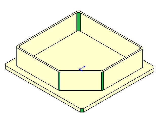
Inside Vertical Edges
It is almost impossible to have a sharp internal corner if the product is milled in CNC.
It is because the material is carved out by a circular spinning tool which will leave a radius whenever it makes a turn at the corners. So for internal edges, the fillet is must have feature within the reason.
As we clear about this, your next question should be what is the radius of the fillet? It is best practice to have a radius of the internal edges to be slightly bigger than the cutter tool your machinist will use.
Outside Edges
Depends on the design requirement you need to make a call whether to go for filleted or chamfered edges.
If outside is not critical to your design you can break the sharp corners by simple chamfering. Anyway chamfering is the general machining practice.
In case you want to give your product more appealing look, you can give fillet all around the edges but mind your radius size. Bigger the radius, lesser the problem.
Most of the internet resources often overlook the fillet requirement for sloped or angled surfaces.
Above explanation is only for vertical walls, but when it comes to sloped surfaces, you need to understand how contours can be machined in general 3-axis CNC. The angular surface requires what you can call as 3D machining.
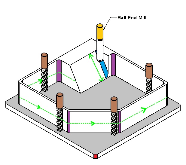
The first operation will be rough cut with end mill followed by the finishing operation by ball end mill. When ball end mill moves near the corner, it leaves around edges.
The chamfer on the hole:
Chamfer around the edges of the hole is recommended. This will help in smoother pin movement and fasteners insertion.


Discussion about this post