


Geometric Dimensioning and Tolerance (GD&T) is the symbolic engineering language used by mechanical designers, manufacturers and inspection personnel to communicate and integrates the functional requirements of the part into the tolerances. So it is not just about the symbols as we see.
GD&T takes out the friction between design and manufacturing engineers. Good knowledge in GD&T helps engineers to appreciate the impact of design intents have on manufacturability, cost, proper dimension specification without tolerances that may be smaller than requirement etc.
In this post, we set a base camp for you to know about GD&T and its important concepts.
Why We Need GD&T?
In the early days of the Industrial Revolution, there were no practices of tolerances. Industries made the parts as per the required dimension as best they can do. Mostly these parts are not interchangeable.
Eli Whitney from Massachusetts popularized the idea of interchangeable parts for the firearms. He builds ten guns with similar parts and mechanisms which can be assembled and disassembled interchangeably. He just used the simple idea of accepting parts produced within an acceptable deviation from the specified dimension (Toleranced Dimension).
But the only problem is toleranced dimensions are not perfect. A toleranced dimension defines size but not the location.
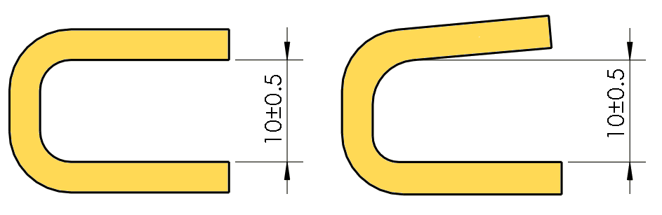
For example, in the part shown below the distance 10±0.5 between the two legs is a location even though the engineer’s intention is to denote the size. We need datum or reference as an origin. If a manufacturer follows this directly toleranced dimension, he will not make the two surfaces parallel.
In below drawing, the part is completely defined with directly toleranced or ± type dimension. This is subjected to a lot of misinterpretations when it goes to the shop floor for manufacturing.
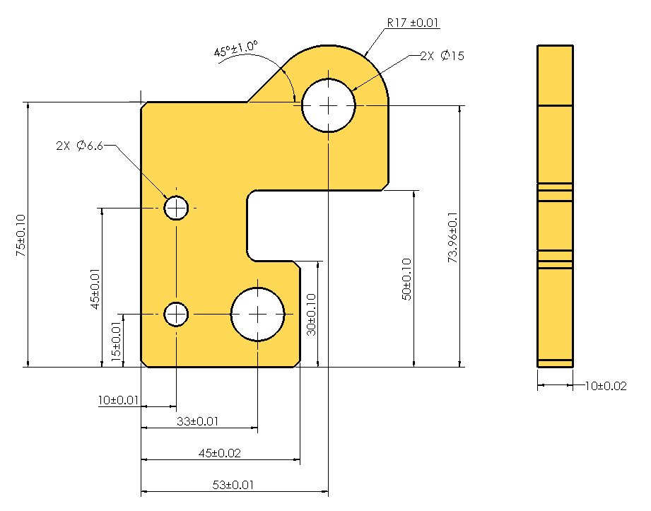
This drawing does not define the requirement of flat or square surfaces. The verification of the product will be the problem. It doesn’t answer the questions like from where we should set the origin? What is the tolerance for the overall length of this part? Whether the two surfaces opposing each other?
So as you see here, in order to produce the parts as per design intends we need geometric tolerancing (GD&T).
GD&T Concepts:
When it comes to GD&T, there is a lot of information available describing how to apply GD&T to the drawing. In this post, we cover some important rules, basic concepts and GD&T symbols that set you up containing:
- Datum Reference
- Feature Control Frame
- Basic Dimension
- Maximum and Least Material Condition
- GD&T Tolerance Type and Symbols.
Datum Reference
Engineering drawing must be interpreted by everyone in exactly the same way to achieve a quality part that suits the design requirement. Implied datum in plus/minus tolerance is not clear (Implied datum is nothing but the assumed origin to fit the part in an imaginary coordinate system).
In order to share a common concept of origin, design engineers, manufacturers, and inspection personnel, proper datum should be defined. It is the communication tool among these three people.
These planes are mutually perpendicular planes which theoretically perfect. There is the leader in this group and also the followers (A-B-C).
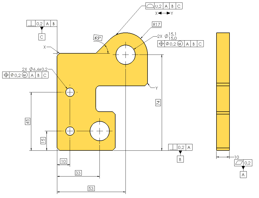
Feature Control Frame
It controls the features (holes, slots, tab, pin etc.). It is denoted by the compartments with the specific requirement in it for the features called in the drawing. The first compartment or box contains geometric characteristic symbols (flatness, circularity etc.). In the drawing, it states that whether the feature is flat or not, perpendicular or not etc.
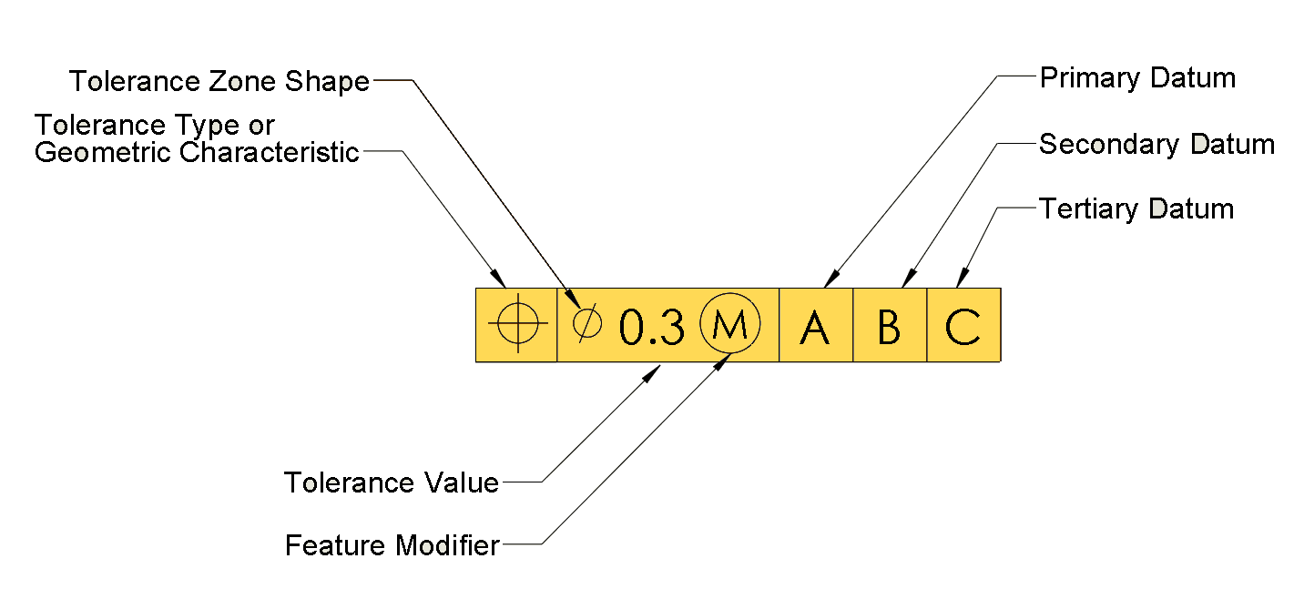
Note: In case if we need to specify two features then there must be two feature control frame or composite tolerance.
Basic Dimension
To control the feature with tolerance at first we have to establish theoretically true value to define the form, size, orientation or location of the part. For example, to control the profile of the radius with the tolerance, we should make the radius as a basic dimension.
Basic dimension is denoted by enclosing dimension in a box. As a designer, you can denote exact location of holes you think it suppose to be. To denote this you need to enclose hole location dimensions in rectangle box.
Note: When we define feature with basic dimension, there is no accumulation of tolerances. The default tolerance, we mention generally in the drawing, will not be applicable to basic dimension.
Material Condition
True design engineers love it. This allows engineers to clearly communicate their design intent to manufacturers. This material condition will give additional/bonus tolerance to the feature.
Maximum Material Condition – MMC: It is a material condition where the feature (Holes, pins etc.) contains maximum material with the specified limit of size. (Hint: If the size of the hole is small then the material will be more)
Least Material Condition – LMC: It is a material condition where the feature (Holes, pins etc.) contains minimum/least material with the specified limit of size. (Hint: If the size of the hole is large then the material will be less)
GD&T Tolerance Type and Symbols
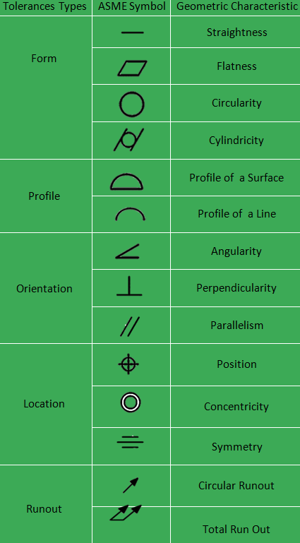
Parts we produce do have characters just like us. If we control those characters within an acceptable limit, we can use it for our purpose. There are 14 characters. We can group them into 4 groups as form, orientation, location, and runout. Below table shows the symbol and its purpose.
Form Tolereance
Flatness – It sets up the condition for surface to be within two parallel imaginary planes (tolerance zone). It is 3D control. Read more about Flatness here.
Straightness – It is condition where the surface need to be within two parallel lines (tolerance zone). It is 2D control. Read more about Straightness here.
Cylindricity – It is a condition for cylindrical surface to be within two concentric cylinders (tolerance zone). Read more about Cylindricity here.
Circularity– It is a condition for cylindrical surface where at any cross-section, the ciruclar elements must lie within the value of two concentric circles. Read more about Circularity here.
Orientation
Perpendicularity – It applies to any surface, mid-planes, or axis which need to at 90° with reference to datum.
Parallelism – It applies to any surface, mid-planes or axis which need to at 180° with reference to datum.
Angularity – It applies to any surface, mid-planes or axis which need to at custom or required angle with reference to datum.
Location
Position – It sets up the condition for the location of the features with tolerance zone within which axi, mid-planes or centre must lie.
Profile of a suface – It is 3D control in case of profile tolerances. It controls the orientation, shape, size and location profiles with boundary condition with reference to datum.
Profile of a a line – It is 2D control in case of profile tolerances. It sets up the condition with tolerance zone of series of cross section all along the profile
Runout
Total runout – It is 3D control which applies through out the surface elements to control orientation, taper, straightness, co-axis, circularity.
Cirucular runout – It is 2D control which applied to the individual cross-section to control eh co-axis, oreintaion and cirularity alone.
Location of derived median plane
Concentricity – It is the 3D control with cylindrical tolerance zone within which the clusters of opposing median points must lie.
Symmetry – Similar to the concentricity, it is the 3D control with tolerance zone of tow parallel planes within which centre plane should lie.
How to Apply Geometric Tolerancing?
We have come up with some general guidelines for beginners to apply geometric tolerancing.
- Follow the Rule#1 which is to define the size of the features (Boss, pins, slots, holes etc.) with Plus/minus tolerances or limit.
- Apply form tolerances (flatness, straightness, cylindricity, circularity) to set the part to define the datums
- Choose your datum wisely based on your part functional requirement as necessary.
- Now introduce Basic Dimension to locate the features (Holes, slots etc.) in your part.
- Apply position tolerance with respect to datums and material condition wherever necessary.
- If your design needs a profile of the surfaces to be controlled, then specify the profile tolerance.
Congratulation, you have successfully applied GD&T in your drawing.


Discussion about this post