


What do you mean by Flatness?
Flatness in metrology and GD&T is the requirement for the surface which controls all the surface elements within the two parallel planes defined by tolerance zone.
Flatness refines the form of the individual feature of the component. There is no datum requirement for this. There are two type of flatness controls just like Straightness – Surface Flatness and Median Plane Flatness. Both use same GD&T symbol. Depends upon where you place the feature control frame determines which type of Flatness is applied.
Surface Flatness – This is the most common type. It controls only the indicted surface. MMC/LMC is not allowed. This type is applicable if you place the feature control frame on the surface.
Median Plane Flatness – This is used to control the mid-plane of the features like slots, widths etc. You can apply MMC/LMC.
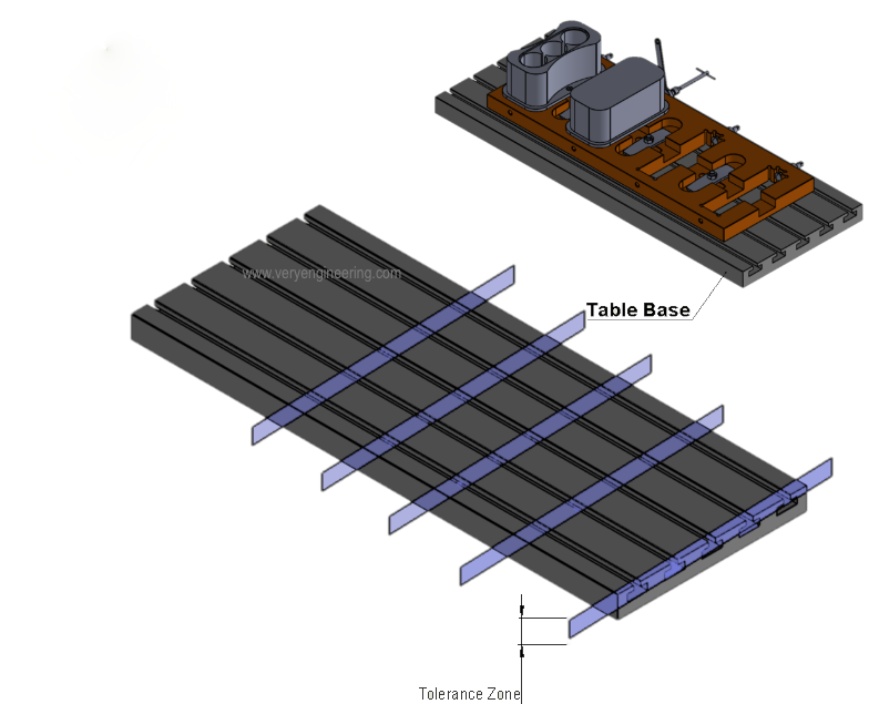
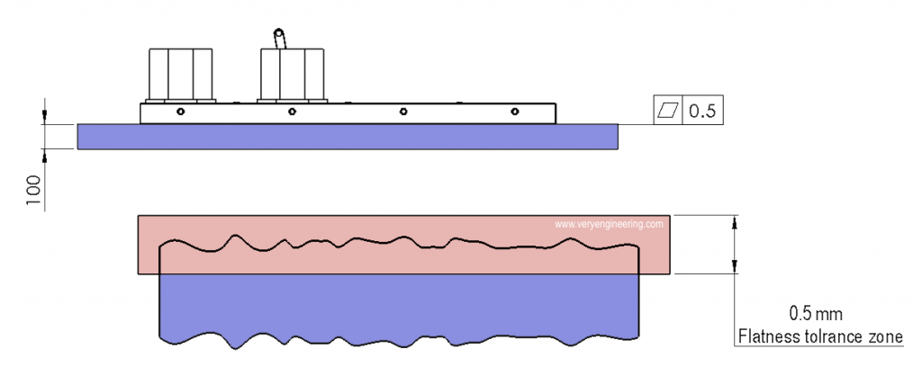
Below illustration shows how the flatness controls any point element on that particular surface with tolerance zone of 0.5mm thickness
What is the flatness symbol?
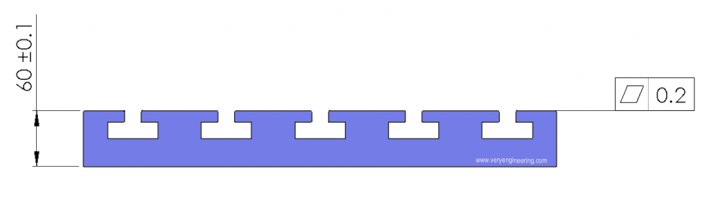
Below image shows the flatness symbol with feature control frame.
How is flatness calculated?
The flatness geometric tolerance value is calculated based on the size of the feature you want to control and also the size of the tolerance zone.
Often when you control the surface with flatness, that particular surface is used as primary datum feature. It is because flatness will minimize the instability make into near perfect feature to use as reference. So keep in mind that when you apply Flatness tolerance as 0.2mm then all its relative features will instable within the limit of 0.2mm
Reasonable flatness tolerance
You have perfectly designed your part in CAD and produced the pretty good drawing with GD&T. But how to select the reasonable tolerances without burn a hole in your budget. Consider the following points to arrive at the reasonable flatness tolerance.
- Understand the process capability of different manufacturing process like milling, drilling, reaming, band saw cutting etc. Each process have tolerance limitation.
- Tolerance with respect to component size for various manufacturing process.
- Production time increases exponentially in case of tight tolerances. We have consider the production time to achieve the tolerance
How to check the flatness of a Surface?
Selecting flatness verification procedure is based on many factors. Each process is well suited for different scenarios like total no. of parts we need verify? Batch verification? Whether it is loose or tight tolerance? Equipment availability etc. Below are the few examples of how the flatness checking is done.
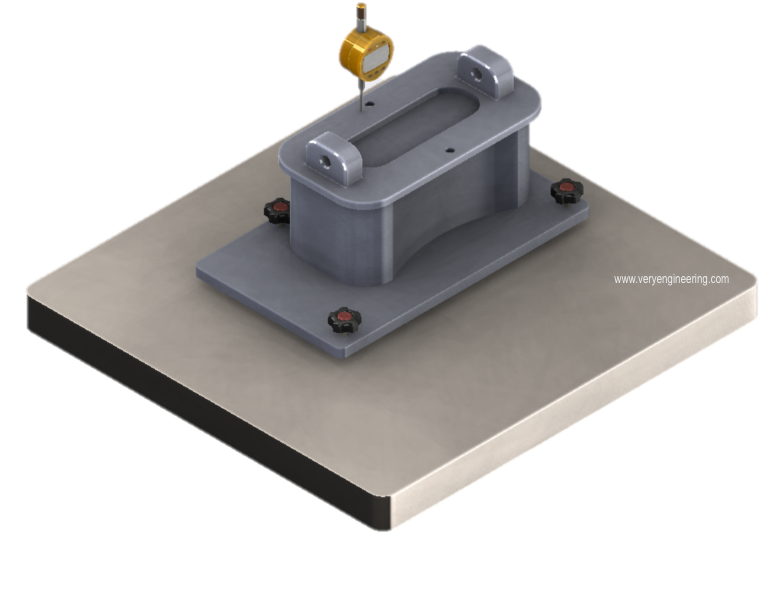
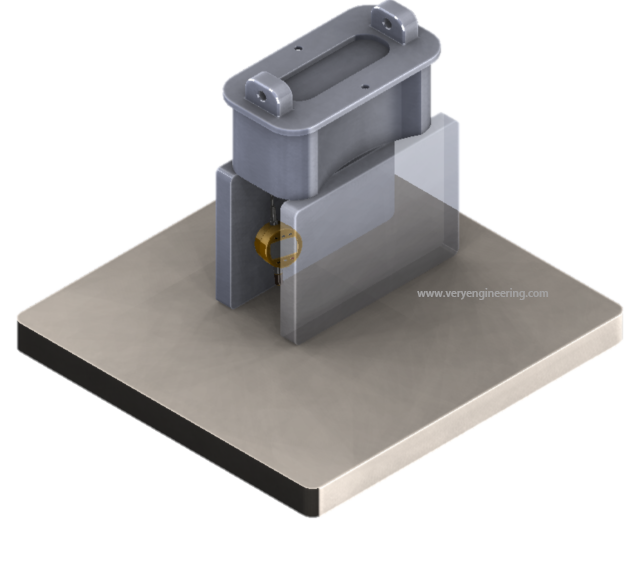
Using Level plate and surface Plate – Component is placed on the level plate which is perfectly levelled on surface plate using the adjusters in level plate. The dial indicator moved over the surface and the readings will be checked against tolerance value.
Using gauge blocks – Here components will be rested on gauge blocks of same height. Dial indicators will be moved underneath of components to verify flatness.
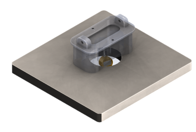
Using dial indicator from underneath of surface plate – Dial indicator will access the component through hole in the surface plate. This is good in quick process check.
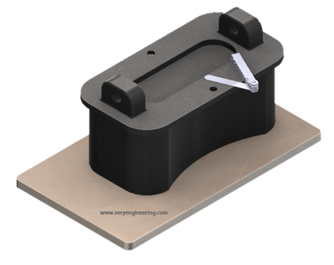
Using Feeler gauge – Component will be placed on the surface plate and flatness is checked visually using feeling gauge. Note that this procedure is best suited for large tolerance value.
There are many other ways to check the flatness like using CMM, light bands etc.
Flatness Application
Sheet metal
Sheet metal is often controlled with Flatness tolerance. This not only control the rock but also the allowable mechanical stress which deform the shape of the sheet metal like in case of parts that will be welded (thermal stress), bolted (bending due to too much torque) or screwed.
Note any feature requirement comes with price tag on it. Sometimes to keep it simple, we can avoid the flatness and just keep simple ‘NOTE’ in your drawing like
‘AS PER MANUFACTURE’S DISCRETION BUT SURFACE SHOULD NOT BE CONCAVE OR CONVEX’
Flatness for Assemblies
Flatness can be used when you want to control the gap or fit between the two parts. For example, when you assemble to parts, if the mating surface is controlled with flatness tolerance value of 0.1mm then it will leads to the gap of 0.2mm between them.
Flatness vs. Straightness
Flatness includes Straightness. Both are identical in way but flatness is controlling the surface with 3D tolerance zone with two parallel plane and straightness controls the 2D line element with tolerance zone of two parallel lines. You don’t need to provide straightness tolerance on any line element of surface which is already controlled by flatness.
Flatness vs. Parallelism
Don’t get confuse between Flatness and Parallelism. Remember, parallelism is the orientation tolerances which controls the feature if you want that particular surface to be 180 degrees to the reference or datum plane. Flatness is just refinement of the size of the feature which don’t need datum
Flatness vs. Profile
Flatness controls only flat surfaces wherein profile tolerance controls the profile the component by forming uniform boundary frame with respect to the datum plane. Note that profile tolerance may or may not requires datum plane
FAQ on Flatness
No, you can’t. Remember surface finish controls the peaks and valley of the surface in localized area and can be applied to round or curved shaped parts. But Flatness, can only be applied on the surface which are flat.
Flatness doesn’t need any datum as it not related to any other feature just like Straightness and other form tolerances.


Discussion about this post