


Hello there,
Here we will show you some of the aspects engineers should take into consideration when designing plastic parts for injection molding. It is important that you understand the main methods used today for manufacturing plastic parts. The following are the main plastic manufacturing process.
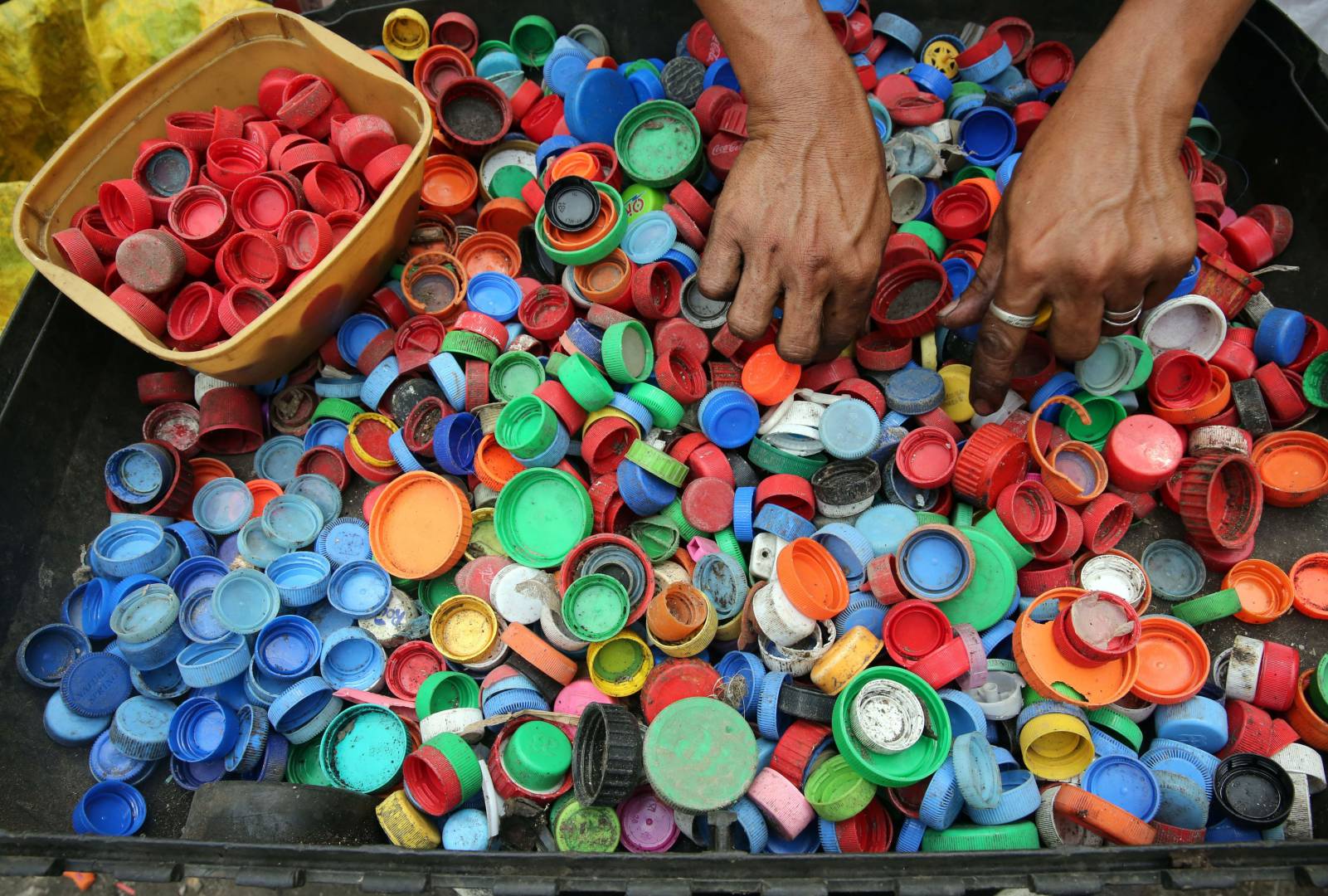
How products are made out of plastics?
Injection Molding:
Injection molding is a manufacturing process commonly used for fabricating items from cell phone cases and toys to automotive body parts, water bottles, and containers. Essentially many of the plastic parts that we use in every-day life are injection molded. It is a quick process to create a mass amount of identical plastic parts.
Extrusion Molding:
Essentially, it is not much different from squeezing toothpaste out of the tube. In this process, we make parts of the continuous length and uniform cross section. Common examples of extruded parts are plumbing pipes, door insulation seals, optical fibers, and steel or aluminum I-beams, spaghetti.
Blow Molding:
Blow Molding is a manufacturing process that is used to create hollow plastic parts by inflating a heated plastic tube until it fills a mold and forms the desired shape. Common examples are water bottles, plastic containers etc.
Rotational Molding:
Rotational molding offers a second option for manufacturing hollow objects. In rotational molding, the plastic powder goes into the mold before heating.
Among the above manufacturing process, injection molding is commonly used.
Let’s focus on Injection molding…
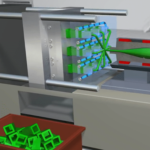
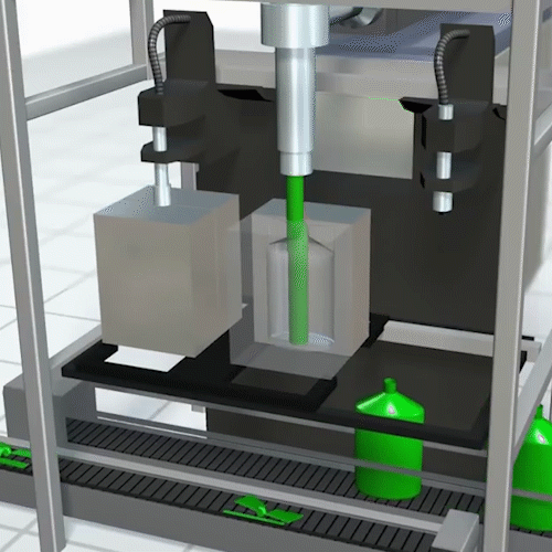
What is Injection Molding?
The injection molding process melts resin pellets inside the injection machine with a heated barrel. An auger moves the plastic forward and ensures an even mix of melted plastic. The machine then drives the melted plastic into a metal mold. The plastic fills the mold and results in a solid plastic part or product.
Must follow guidelines when designing for Injection Molding.
It is important when designing products for injection molding that you consider how they will be formed in the machine, how they will be taken out of the machine, and the structure of the final product. Some important guidelines are:
Part Lines:
A parting line the line on the part where cavity and core meet. You will most often see the difference in draft angles from each mold half from the parting line.
The mold designer’s goal is to choose a location for the parting line that will create the most robust tooling design, while at the same time making it less noticeable. The parting line usually needs to follow the outside contour of the part, and it needs to allow all the features of the part to clear the tooling in the direction that the mold opens.
Injection molded parts also need to be drafted for release from the mold, and the locations and directions of this draft will influence the parting line location.
Parting line placement will also affect the cost of the mold. The simplest and strongest parting line is one that exists on a single, flat plane. However, because of the complexities of many injection molded parts, this type of parting line is not always possible.
Draft:
Plastic injection molded parts are created by injecting liquid plastics into mold cavities. This liquid is also injected over cores, which means they require draft in order to release from the mold.
The Draft is a term used to describe the amount of taper on the vertical walls of the plastic part. Without a draft, a part will either not eject from the mold – or it will sustain damage during ejection. Typically, draft angles between 1° and 2° are required. These also vary depending on part restrictions and specifications.
Wall Thickness:
Plastic parts should always be designed with a nominal or consistent wall thickness. Every injection molded part shrinks as it cools and the differences in the thickness of the part will cause the part to shrink at different rates.
Thicker areas of the part will shrink more than in those thinner areas. This has been known to result in the deformation of the part. Another issue is sink marks, which are areas of the part that is “dimpled” due to excessive shrinkage. The solution to this problem is to remove or “core out” thick areas of the part to avoid these conditions.
Part designs with nominal wall thicknesses may not be as strong as a thicker part. When this is the case, ribs are used for strength. When utilizing ribs on a part – their thicknesses should never be less than 70% of the nominal part thickness in order to avoid sink marks. As with other vertical surfaces on the part – the ribs should also have draft.
Bosses, Ribs, and Gussets:
The most common variety consists of cylindrical projections (bosses) with holes designed to receive screws, threaded inserts, or other types of fastening hardware. Under service conditions, bosses are often subjected to loadings not encountered in other sections of a component. Provide a generous radius at the base of the boss for strength and ample draft for easy part removal from the mold.
- Minimum Radius at Base of Boss – The recommended value for radius at the base of a boss is 0.25 to 0.5 times the nominal wall thickness.
- Spacing between Bosses – It is recommended that spacing between bosses should be at least 2 times the nominal wall thickness.
- Radius at Base of Hole in Boss – It is recommended that the radius at the base of the hole in boss should be 0.25 to 0.5 times the nominal wall thickness.
- Minimum Draft for Boss OD – The recommended value for the minimum draft on the outer surface of the boss is greater than or equal to 0.5 degrees.
- Minimum Draft for Boss ID – It is recommended that minimum draft on the hole in boss should be greater than or equal to 0.25 degree
- Wall Thickness of Boss – Wall thicknesses for bosses should be around 60 percent of the nominal wall to minimize sinking.
- Standalone Boss – Bosses and other thick sections should be cored. It is good practice to attach the boss to the sidewall. For better rigidity and material flow, a boss should be connected to the nearest side wall.
Radius & Fillets:
The only place you want sharp corners on your part is parting lines that are naturally created. Radii should be added to angles to prevent sharp corners. Corners can lead to stresses, limit material flow, and often reduce part strength.
Keep in mind that radiused corners should maintain the same wall thickness, which means that if the inner r=½ thickness then outer R=3*½ thickness.
Material and Thickness:
The goal is usually to choose the thinnest wall possible. Thinner walls use less material which reduces cost and take less time to cool, reducing cycle time.
The minimum wall thickness that can be used depends on the size and geometry of the part, structural requirements, and flow behavior of the resin. The wall thicknesses of an injection molded part generally range from 2mm – 4mm (0.080″ – 0.160″). Thin wall injection molding can produce walls as thin as 0.5mm (0.020″). The chart below shows recommended wall thicknesses for common injection molding resins.
Ejector Pins:
Ejector pins help safely remove parts from molds after they have been made. We need to properly locate and use those pins. Ejector pins apply a force to eject a part from the mold, and, in some cases, can leave marks. The goal for engineers and molders is to design and position pins to minimize their effect on parts.
Round ejector pins with flattened ends perpendicular to the direction in which the pin moves are common. To be effective, the pins need a flat “pad” on the part to push against, and the pad’s surface must be perpendicular to the direction of pin movement.
If a pin needs to act on a part surface that is not parallel to the pin-end, there should be a pad, provided it is in the same plane as the pin-end rather than that of the part surface. Because it is in a different plane than the part surface, the pad may be raised slightly above the part surface or recessed slightly below the part surface at one edge.


Discussion about this post