


What is Design for CNC machining?
Design for CNC machining is just an act of balancing part design to meet CNC machining capabilities which can fast-track the production, lesser lead time and reduced manufacturing costs.
When it comes to CNC machining, not every design can be manufactured easily. Perfect design is not what you can do in CAD model, it is how easily and effectively you can produce it. If you want to cut the manufacturing cost or speed up the production, you need to focus on term ‘Design for Manufacturing and Assembly’ (DFMA).
In this post, we will go through simple but effective design tips while we design the part for machining.
1. Choosing Correct Material
You must to know how to classify the material based on their various properties. But as far as machining, concerned factor is how fast the material can be machined.
In material, you won’t save money not only by choosing cheap material but also by reducing machining cost to machine that material. Sometimes you can choose expensive material and still reduce the overall cost by reducing machining time.
For example, by choosing expensive aluminum alloy like 7076 over steel you can save the money as aluminum can be machined much faster than Steel on most of the CNC machines
Suggestion: Harder the material will take more machining time. If design permits, go for soft material.
2. How the Part Will be Hold During the Machining?
You should be asking yourself some improtant question on how to hold the part. Your design features must be designed in a way to cut the number of setups needed to contact all sides of the part. Avoid designs which need custom fixtures and jaws to hold the part into vice.
3. Internal Fillet
When your part is machined in CNC vertical or horizontal milling machine, all the vertical corners should have a radius. This is because as cutting tool have cylindrical shape , it’ll leave round corners when passing through corners. If you want to be machinist friendly designer, then as thump rule you should maintain radius of atleast 1/3rd of the depth of the cavity and use the same radius in all the corners.
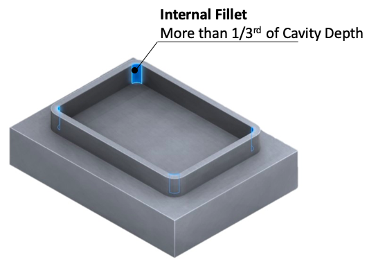
If you maintain the small radius you should be ready to pay more for parts. It is because tool will be required to run at lower speed at multiple passes to achieve the small radius.
In case if you 90-degree corner angle, then instead of using small radius it is better to have Dog bone corners. Please check more about fillet design in this post. Fillets-and-chamfers-how-to-choose-it?
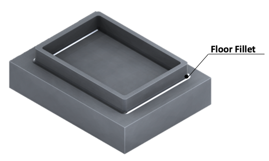
4. Floor Fillet
Only in absolute necessary use floor radius else avoid it. It is difficult and time consuming step to remove material in the floor. If you need to have floor radius then maintain radius smaller than vertical corner radius so that same tool can be used to remove the material in the floor. Best practice is to use standard bull nose mill radius so that your machinist easily select the tool.
Suggestion:
- Floor Radius should be less than wall radius.
- Avoid floor fillet.
5. Cavity
Do you know if you double the length of the cutting tool, then tool deflection will increased by 8 times. This means shorter cutting tool with large diameter will take less machining time. So we need limit the depth of the cavity/pocket for optimum machining time.
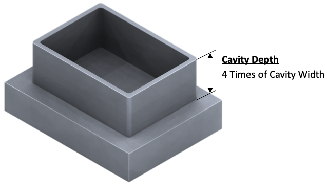
It is recommended to have cavity depth to less than 4 times of the width of the cavity. If you still need the larger depth, then go for the variable depth to allow using different tool.
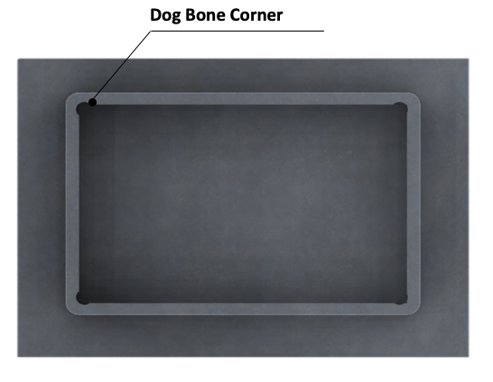
6. Dog bone corners
In case you need 90˚ corners when cavity will get assembled with straight rectangular part, use radius cut like shown in picture. This is better than having small radius.
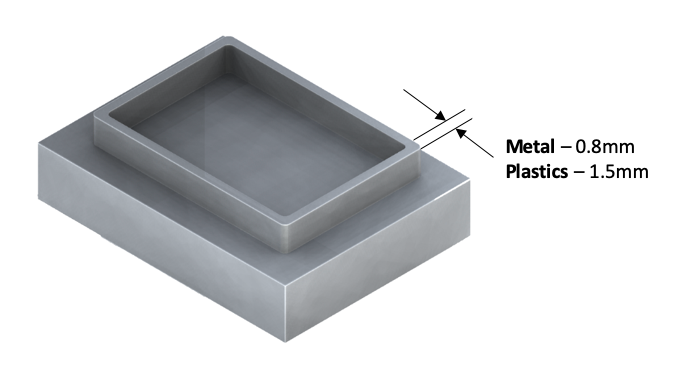
7. Minimum Wall Thickness
Engineers tends to optimize the components weight in terms to reduce total weight. One way to achieve this by having thin walls as much possible. But this need to in certain limit. The reason is thin walls while machining tends to vibrate as it has low stiffness. This makes harder for machinist to maintain tight tolerances as they need to run the tool at low speed.
In order to keep the machining cost low it is recommended to have minimum thickness as per the material. Thin walls lesser than above limit is possible given that walls are supported on either end. These rib support adds addition support during machining without much affecting cost.
- Metal – 0.8mm
- Plastics – 1.5mm
8. Threaded Holes
In practice, there are many ways to make threaded hole like form tap, thread mills, cut tabs, die etc. Designers need to follow below guidelines for effective design.
Recommended Thread Size:
Avoid small thread size. It is recommended not to go below M2 size. As the small tab and die tools are proved for breakage during tapping process.
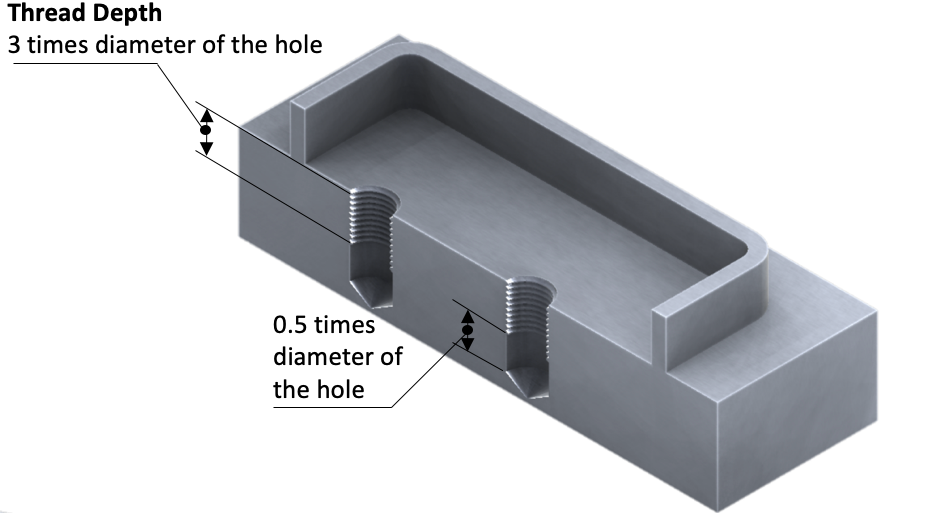
Recommended Thread Depth:
- Recommended thread length is lesser than 3 times the nominal diameter of the hole. Don’t be liberal with thread length. Always go for thread length as required by design.
- Note that it is hard to tap throughout the pilot hole. It needs change of tab type. So, it is recommended to have at least 0.5 times of tap diameter beyond the thread depth.
9. Stock size
It is good practice to select the stock size slightly more than your required size. This is required to hold the part in vise while machining and for finishing operation in your part.
10. Chamfer and Deburr
It is standard practice in machine shop to break all the sharp corners. So, in drawing you can include one common note saying ‘UNLESS OTHERWISE SPECIFIED BREAK ALL THE SHARP CORNERS’.
45˚ Chamfer is standard tool size. As required by design, other angles also possible.
11. Reduce setup
It is very important to consider number of setup your component need in CNC machining. Setup is just number of times the workpiece is rotated to machine the features. Whenever the operator need to remove and rotate the component, he/she need to recalibrate the coordinate. This increase the total machining time. So, keep features in component as relative to minimum setup required
12. External corners
As we mentioned earlier, it is natural process to have radius around the external edges if machining happened around. Take this in your consideration and be liberal with the size.
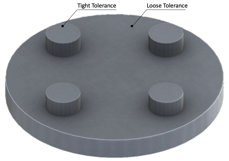
13. Loose those tight tolerance.
Sometimes in your design you need to maintain tight tolerance over large surface area (base plate), If you want to be in machinist good books, instead of maintaining tolerance over large area you can consider of having controlled bosses and leave rest of the area with liberal tolerance.
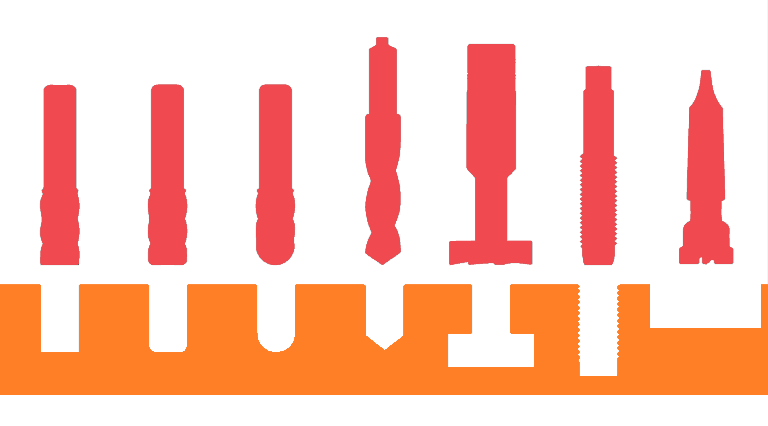
14. Drill Holes
Drilling holes can be done either using standard drill bits or end mill tool. Holes made with drill bits will have conical finish while end mill will have flat finish.
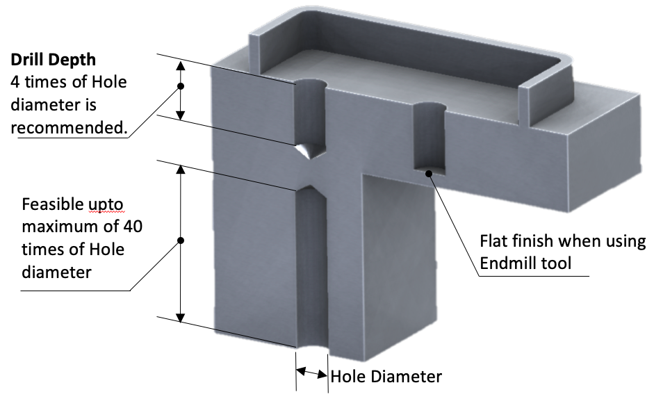
Though Standard drill bit is preferred end mill comes handy if same end mill is used to machine the cavities. There by eliminating tool change.
| Recommendation | |
| Diameter | Standard Drill bit sizes |
| Depth | Recommended 4 times of nominal diameter of tool. Maximum depth can be 10 times of nominal diameter in case of critical design requirement |
15. 3D Profile
3D profiles are required to machine non-prismatic parts such as molds, dies, and consumer products. The first operation will be rough cut with end mill followed by the finishing operation by ball end mill.
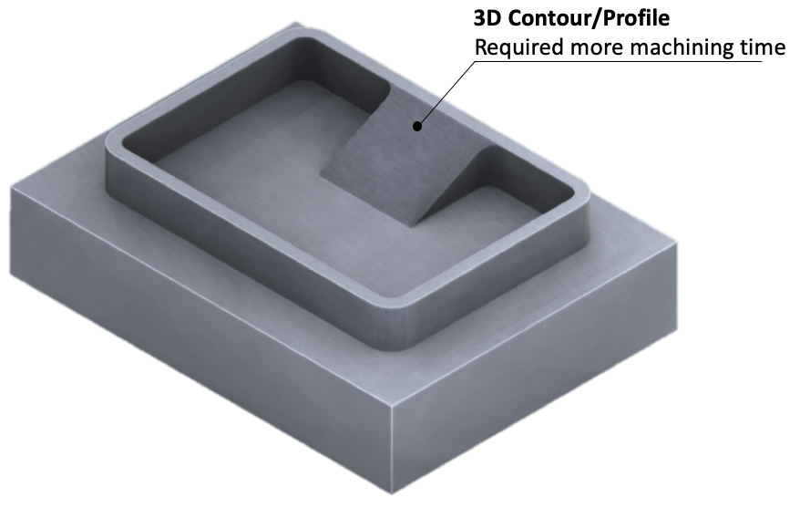
Try to avoid 3D profile cut as much possibe. It’ll slow down the manufacturing time drastically. If at all it is required use largest possible ball end mill to speed up the process.
16. Undercut
In practice there are two types of undercuts one is T-slot undercuts and dovetail undercuts.
Designers should make sure to leave enough room for the tool to pass while designing part for undercut. As rule, you will need at least 4 times the undercut’s depth in between the machined wall and other internal walls.
For T-Slot undercut, the width of the undercut is the defining feature. The width can be between 3mm to 40mm. Use of standard width is highly recommended as non-standard tools will be custom made which will increase machining cost.
Dovetail undercut can vary with angles. The standard angle is 40˚ or 60˚ tools.
The depth of the undercut is the ratio of cutting blade diameter and diameter of the shaft which is 2:1
17. Text and letters
Having text on parts really looks cool but unfortunately, we need to avoid it as it adds cost. There is other effective way to add text like embossing, laser etching etc.
If you really need to use CNC to make text then avoid sharp letters.
It is recommended to use font family like BOLD Sans-Serif e.g. Arial, Verdana, or Helvetica as they have fewer sharp features.
18. How small your feature can be?
You must get familiar with word called micro-machining. This is not cost –friendly word so we need to avoid it. It is recommended your features (Holes, slots etc.) should minimum of 2.5mm to be machined by standard cutting tools.


Discussion about this post