


What is Circularity?
Circularity comes under four type of form tolerances. It controls or refines the circular or sphere features. This forms two dimensional tolerance zone obtained by cutting plane in cross-section of the cylinder within which the all the elements of the cylindrical surface should lie.
Circularity helps manufactures by communicating how far the cylindrical feature can be tapered or barreled.
Circularity Symbol and What Does It Means?
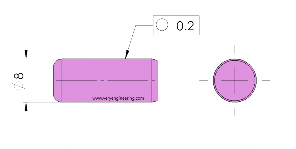
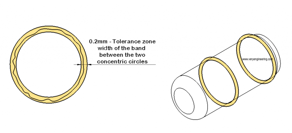
Below is the circularity GD&T symbol. Tolerance value indicated in feature control frame is band distance between two concentric circles. In below case it is 0.2mm of Tol. Zone. At any given cross-section of the feature, circular elements on along surface should lie.
Circularity also represent as Roundness. For rotating parts like Shaft, Bearing, Valves, Pipes, Hoses etc., it is most commonly applicable. By Circularity, you can control the wear and tear or to arrest oil leakage in sealing’s between shaft and hole.
Why we need Circularity?
Circularity eases manufacturing difficulty by providing refinement to the surface by adding circular tolerance and at same time we can increase diameter tolerance. By this both design intention and Process tolerance will be satisfied.
What is Cylindricity?
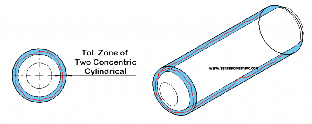
Cylindricity is the extension of circularity which controls the all the points of the cylindrical surface with two concentric cylinders formed from the common axis. It is the combination of circularity and surface straightness. It is most common GD&T tolerance which refines the feature for both round and straightness requirement.
Cylindricity Symbol and What Does It Means?
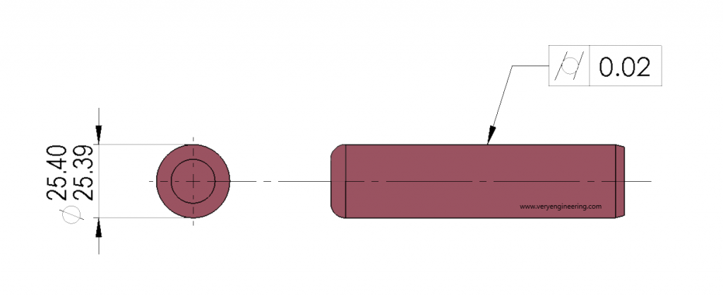
The tolerance zone is formed by two concentric cylinders within which all the cylindrical surface element should lie. The value of the width between two concentric cylinders is defined by tolerance value. Cylindricity application examples are bearings, shafts, dowel pins, bush etc.
Why we need Cylindricity?
Cylindricity offers great manufacturing cost reduction. For example, Bearing design requirement is to be perfectly cylindrical. Meeting this manufacturing requirement during mass production becomes difficult with tight tolerance control all over the cylinder. If we introduce Cylindricity here, we can ease the size tolerance and then do the grinding to refine only the cylindrical surface.
Datum and Modifies requirement for Cylindricity and Circularity
Both the form tolerance are not related to any other feature of the components, so we don’t need the datum for these.
They also controls the surface in relation to the top surface of the cylinder, so they don’t require MMC, LMC and RFS modifiers.
How they are related to other GD&T tolerances?
The tolerance zone for circularity is the circle, therefore it does not include any other GD&T tolerances. Providing Cylindricity tolerance would include both circularity and straightness. It is nothing but the extension of circularity in 3D form.
How to measure Cylindricity and Circularity?
We need to accept the fact that both tolerance are painful to measure. So use it only when you need it. Most common measurement practice is by rotating the part in Vee Block and external surface feature variance is measured by dial indicator with reference to axis formed by angle of the vee block.
Other precise method of measurements are CMM and roundness machine in which precision spindle in utilized to get the profile of the part in graph.
What is the different between Circularity and Cylindricity?
Like Straightness and Flatness, Circularity is a 2D form of Cylindricity. It controls only the circular elements of the cross-section, not along the length of the cylinder. Its tolerance zone is distance between the two concentric circles.
Whereas Cylindricity controls throughout the length elements of the cylindrical feature
Discussion about this post