


GD&T is the engineering language used by designers/engineers to describes the part in term of geometric perfection and functions. Pretty much function determines the part design and tolerance by the engineers. We written a blog post on beginners’ guide to GD&T. In this post, we go through ’Straightness’ one of the GD&T tolerances.
What is Straightness?
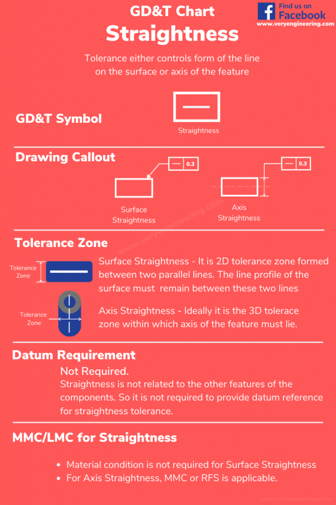
Straightness sets up the condition to control line element either of the surface or the axis. It is the 2D control where two parallel lines will be the tolerance zone. ( IMPORTANT: Mug up on it for your interview. There is high chance you won’t remember upcoming content 🙂)
Let’s connect this understanding of Straightness with one practical application of it.
Importance of Straightness
Let’s understand the importance of straightness through below case study.
The part in our case is a sleeve bearing used in a DC motor. Two of those bearings will be assembled into the motor end to hold the rotating armature shaft. The Straightness of the surface and straightness of the axis in the shaft is critical to the fit and function of this assembly.
When it was suggested that straightness be added to the shaft in order to control its fit relative to the inside surface of the bearings, the design engineer not much worried as the vendor who had submitted sample bearings which had passed his design functions with awe face.
Our engineer believed that his drawing is perfect without straightness as the sample part submitted by his vendor as per the drawing, passed the test. Being a vendor what you would do to win 10000 parts. of machine job? You would produce best sample shaft with as near perfect as possible and definetly not representative of production bearings. Our Engineers missed this viewpoint and given order to this vendor which resulted in huge loss.
Type of Straightness
Here our engineer should have created drawing with straightness control of surface of the shaft and its axis. See here we talked about two things. There are two type of Straightness form controls – Surface Straightness and Axis/Line straightness. Depends on how we place the feature control frame determines the type of straightness applies on the drawing.
- Surface Straightness – Surface Line on the cross-sectional plane of the shaft must lie between the 2-dimensional tolerance zone
- Axis/Line Straightness -The axis of the shaft must line within the cylindrical tolerance zone which will control axis straightness
Surface Straightness
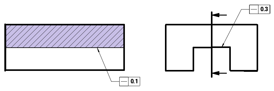
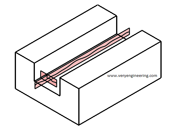
In surface straightness, feature control frame is placed on the surface where control in required. This indicates the tolerance zone on the surface within which line element of the feature must lie. See below image for visualization of tolerance zone on the surface. In this image tolerance zone is the two parallel lines of 0.3mm apart.
Surface Straightness in two direction – Earlier we mentioned Straightness is the 2D control, so the condition applies only in one direction. If you like to control the surface in other direction then we need to place the condition in different views.
Surface Straightness on cylindrical feature – Surface straightness can be applied to cylindrical feature too. For example straightness applied on the surface of the dowel pin defines the condition that all the longintudinal elements of the pin surface must lie with the twe parallel and longitudinal lines (tolerance zone). This will control the dowel pins bending and barrelling.
Axis Straightness
Axis straightness sets up the condition to control the axis of the cylindrical features. It forms a cylindrical tolerance zone in which the axis must lie. This will allow us to control the size of the pins at given location .
FAQ on Straightness
We don’t need to provide the datum for Straightness as it is not related to any other features.
We dont need MMC for Surface Straightness but it is required for axis straightness so that assembly fit works better manner.
Discussion about this post